Author Archives: admin

  • -

The progression of surface rolling contact fatigue damage of rolling bearings

Category : Technical Articles

The mechanism of surface rolling contact fatigue in rolling bearings is investigated by means of dedicated experiments and numerical simulations of the damage progression.

Rolling contact fatigue (RCF) is a typical failure mode in rolling bearings and similar types of machine components. The fundamental work in RCF is due to Lundberg and Palmgren [1], [2]. The Lundberg-Palmgren theory was mainly focused on subsurface rolling contact fatigue, and it relies entirely on ideally smooth Hertzian stress calculations. Surface rolling contact fatigue (SRCF) instead involves the area close to the surface of the contact (a few microns deep) that is strongly affected by local surface traction and stresses originated from geometrical features of the surface such as roughness, profile deviations, indentations, etc. The interaction between the elasto-hydrodynamic lubricating (EHL) film and the actual features determining stress risers at the surface is very important in the understanding of surface fatigue phenomena of rolling bearings (Morales-Espejel and Gabelli [3]). In this article, the progression of SRCF is investigated by modelling the contact and the interaction with deviations of the surface micro-geometry that generate stress concentrations. Comparison of the numerical simulations with a set of experimental results indicates good correlation, allowing the formulation of a hypothesis about the underlying mechanisms of SRCF, as well as its inception and growth in rolling bearings. This new knowledge fits very well with the basic idea behind the SKF Generalized Bearing Life Model (GBLM) that separates surface from subsurface fatigue damage [4][5].

Theoretical investigations in damage progression
Often, rolling contact fatigue damage originated around surface microgeometry features develops into a spall. Spall propagation, in its advanced form, is strongly influenced by macrogeometry aspects – for example, the evolution of the raceway contact geometry and resulting overall stress field in a rolling bearing. Several researchers have studied spall propagation in rolling bearings in the attempt to associate the mechanical aspects driving the damage progression.

A recent investigation carried out by the present authors [6] has studied SRCF propagation of predented rolling bearings, both with a model and experiments, concluding that the mechanisms involved in ball bearings require the consideration of lubrication conditions and the interaction of stresses between the surface and subsurface to understand the development of the typical V-shaped cracks along the raceway, differently from the initial transverse damage growth observed in roller bearings that can be explained sufficiently with only dry contact assumptions.

Experimental observations in damage progression
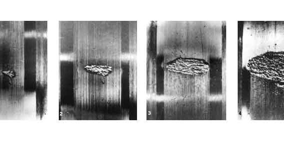
Snare [7], in his statistical analysis of bearing reliability, monitored the propagation of a spall in a cylindrical roller bearing, showing the clear progression of the damage across the raceway before the spall starts to propagate along the raceway. Fig. 1 shows the experimental tests of Snare.

Current understanding
From the theoretical and experimental investigations found in the literature, at least two distinctive spall propagation phases from surface defects are clearly recognized. The first one is when the spall grows across the raceway at a more or less slow rate, and the second is when it grows along the rolling path in a more accelerated fashion. The reason for the across-raceway propagation of the spall, in its initial phase, is understood as a consequence of the higher stresses present at the diametral edges of the spall – that is, along the direction orthogonal to rolling, compared to the stresses at the spall leading and trailing edges.

The behaviour of the spall inception and propagation on ball bearings (fig. 2) and roller bearings (fig. 3) is strikingly distinct. Surface-initiated spalls in ball bearings initially develop with a characteristic V shape at the trailing edge of the indentation, rapidly growing in the rolling direction with the detachment of raceway material from the V-shaped area. The growth of the spall is observed in the rolling direction, which is the direction opposite to the direction of friction and slip present at that location (fig. 2). Surface-initiated spalls in roller bearings initially propagate at the two sides of the original initiation spot, growing across the raceway before expanding along the raceway (fig. 3).

The objective of this article is to shed further light on the progression of surface-initiated fatigue damage of roller bearings. This is to understand via modelling the driving mechanisms behind the damage propagation as observed in the experiments, as a continuation of the work reported by the authors [3], on the initial damage phase, but now focused of the propagation of this damage.

Experimental work
Experiments were conducted on standard tapered roller bearings; see table 1.

Tapered roller bearings were artificially indented using an indentation load of 1,250 N and a 1 mm diameter tungsten carbide ball indenter. This load provided dents with a diameter of 400 µm, 30 µm dent depth, and a raised edge height of about 2 µm. The experiment consisted of eight equally spaced indentations around the circumference on the inner ring of the tapered roller bearings. The dents were also spaced at 0.5 mm steps across the raceway, starting from the raceway edge. However, in this article, only the progression of damage of the dents located at the centre of the raceway will be discussed in detail. Under the operating conditions given intable 1, the axial load provided a Hertzian width in the rolling direction of about 142 µm, which is substantially narrower compared to the dent diameter. The experiments were run at different numbers of revolutions to observe the progression of the fatigue damage, resulting from the stress concentration and lubrication conditions of the dents.

Fig. 4 shows some experimental results about the progression of the dent spalling in the tapered roller bearing for an increasing number of revolutions. The spall initiated at one side of the dent and then progressed towards the two sides of the dent across the raceway – that is, along the direction orthogonal to rolling. In fig. 4(b) an approximated contact ellipse was drawn for comparison with the final spall. Several inner rings were monitored by periodic microscopic inspection performed on each bearing, at about 5 million revolutions apart, to detect the initiation and propagation phase of the spall. Each dent was microscopically inspected and photographed as a function of the number of revolutions performed in the test. The initial development and further progression of the spalled area around the dent were measured by digital image processing of the collected microphotographs from several individual dents. The results of this detailed investigation provided very precise information about the initial and progressive growth of the spalling damage area against number of revolutions.

All the data collected from the six individual dents that developed spalling damage are shown infig. 5.

A more detailed inspection of the average test data indicates that the progression of the spalled area follows a three-stage process:

1. The incubation time of 50 to 60 million revolutions in which no apparent visible damage can be detected in the bearing raceway; this is about the fatigue rating life of the bearing.
2. The initial damage progression phase, which extends for 30 to 40 million revolutions, as expected, displays an exponential growth of the damaged area.
3. The accelerated growth. This extends for 20 to 25 million revolutions, during which the growth rate substantially increases (more than twice compared to the previous period).

Damage propagation model
Calculation of the damage in the rolling contact is carried out by modelling in the first instance the initial indentation of the raceway. This is done using a parametric analytical function that closely reproduces the shape of the actual dent.

The dent geometry is then included in an overrolling contact model to reproduce the Hertzian cycling stress of the actual test bearing. The damage progression calculation is performed using the basic surface fatigue and detachment model developed previously by Morales-Espejel and Brizmer [8] and fully described there. However, some modifications and adaptations were also introduced. For instance, the routine for wear calculation, as described in [8], was switched off to accelerate the speed of the numer-ical simulations. The fast lubrication model is switched off, and only the dry contact model is used for situations where the initial indentation is wider than the Hertzian contact in the rolling direction, which is the case for the simulated tapered roller bearing of fig. 4(a). The model is then used in the calculation of the overall pressures and stresses. This approximation is valid because in this case the lubricant is likely to escape from the dent and contact. No generation of hydrodynamic pressure is to be expected at the dent edge region whose pressures can therefore be modelled using the dry contact hypothesis (for ball bearings with wider Hertz contact area, the lubrication model cannot be ignored).

Once the contact pressures are calculated, the stress history is obtained for a series of time steps designed to simulate the passage of the indentation through the rolling contact (see [5]). From this multistep simulation process the fatigue stress history can be computed for further processing by the fatigue criterion in order to estimate the fatigue damage accumulated from the start to the current load cycle. This scheme follows exactly the same data processing introduced by Morales-Espejel and Brizmer [8]. The total damage accumulated up to the current load cycle is calculated following the Palmgren-Miner rule.

When fatigue reaches a critical damage value, the possibility of an onset of material fracturing emerges. The current scheme does not have a detailed crack propagation model; the damage propagation is simulated by simply removing fatigued material. For this purpose, a simple material detachment model [8] was implemented that performs the task of removing the material with accumulated critical damage and material above it. This model contains also a threshold depth (h) from the surface below which material with critical damage is not allowed to detach. This threshold depth can be set up from h = 0 to h = ∞.  Setting h ≥ 0 will allow material below the surface to detach. The current model cannot give a precise indication of the damage growth if the parameter h is not known in advance or if some experimental results are not available, but it can very well describe damage growth ranges as will be shown below. The calculation process is repeated for a given number of load cycles (up to a maximum, typically > 109 overrolling cycles), after which the damage progression history is reported.

Model results
Test data are given in table 1. In this case the dents are wider (i.e., diameter 400 μm) than the Hertzian contact in the rolling direction (i.e., 142 μm); therefore, it will be impossible during overrolling to develop the required EHL pressure over the dent. This will induce a collapse of the oil film at the edge of the dented area. Under these conditions, the effect of the lubricant film can be excluded from the analysis, and the progression of damage can be simulated simply using the dry-contact approximation.

Fig. 6 shows the spall evolution from the initial indentation for an increasing number of revolutions; they also show the progressive changes of the Hertzian pressure and related subsurface stresses. The results of the numerical simulations clearly show the preferential direction of the progression of the spalled area. The damage starts from the dent lateral edges and progresses in the axial direction across the raceway in a similar manner to the one observed in the experiments (see fig. 4). By computing the area covered by the damage and its evolution with the number of bearing revolutions, it is possible to obtain the curve of the progression of the damage area versus number of revolutions of the bearings. This was computed for two threshold depth levels, h, a minimum and a maximum to characterize the scope of the model simulations (hmin just touching the area of maximum orthogonal shear stress around the dent and hmax well beyond that). The resulting damage progression curves are shown with dashed lines in fig. 5. A thin dashed line is the result of the most conservative setting for the estimation of surface-initiated microspalling – that is, minimum value of the threshold depth. Therefore, the simulated results represent a safe bound of the damage, defining the conditions for the maximum expected damage area from any surface-initiated spall.

With the implementation of a maximum threshold depth value, h, the evolution of the damage shown in fig. 5 with a thick dashed line shows a more realistic match with the experimental results. Noticeable is the initial trend of the computed damage area, which shows a stepwise progression clearly matching some of the experimental measurements. This trend achieves a stable growth rate of between 90 and 120 million revolutions; this interval can be compared to the measured initial progression phase of the damage growth of the dent as discussed in the section “Experimental work”.

Fig. 7 shows the damage growth rate of the experiments compared to the one obtained from the numerical simulations, which is 11.5 million revolutions (134 million cycles). This good correlation between the average of the experimental results and the numerical simulations shows the ability of the computation to capture some principal effects of the surface fatigue mechanisms and of the initial spalling progression. In addition, the experimental results indicate an accelerated growth after 100 million revolutions that seems absent from the results of the numerical simulations. A possible explanation of this behaviour is that the generation of a spalled area also results in additional loads due to the dynamic response of the bearing to the spalling damage. At the moment, these additional loads are not included in the model; thus, only the initial spalling damage can be reasonably compared with the numerical
simulations.

In the simulated results the mechanism of the damage progression is also interesting. Because the indentation is a bit larger than the Hertzian width in the rolling direction, the most loaded zone in the raceway is the lateral area of the indentation, where the damage indeed will initiate and progress. This propagation mechanism can also be found in the numerical simulation showing the lateral edge of the spall affected by the largest surface pressures and subsurface stress concentrations (fig. 6). This type of spall propagation seems to be typical of roller bearings.

Discussion and conclusions
Experiments have been carried out on tapered rolling bearings. The raceways of the bearings were indented with predefined hardness imprints. This created a series of surface stress risers from which surface spalls were originated, allowing the detailed study of their inception and progression. An existing model for surface microgeometry fatigue (Morales-Espejel and Brizmer [8]; i.e., surface distress) was adapted to study the surface-initiated macro-spalling process.

The model was applied to gain better insight into the initiation and early propagation phase of the spall. From the computational results it is found that indeed the numerical model can simulate and explain well many of the experimental observations; in particular the experimental results have indicated that in case of the tapered roller bearing, the spall propagates initially across the raceway – that is, along the direction orthogonal to rolling. In general in line-contact bearings, the stresses are higher at the lateral edges of the indentation. These higher stresses drive the growth of the spall across the raceway during the initial expansion of the spall.

From the results of the current work, the following conclusions can be drawn:

1. Pre-indented roller bearings propagate spalls initially across the raceway, driven by the higher stresses found at the edges of the spall along the direction orthogonal to rolling, as previously described in the literature.

2. The presented model describes well the two spall propagation mechanisms. For roller bearing spalls in particular, a good correlation between the model prediction and the experimental measurements is found in the initial spall growth rate.

Acknowledgment
The project was partially financed by the European Commission Marie Curie Industry-Academia Partnerships and Pathways (IAPP) – iBETTER Project.

Μοιραστείτε το άρθρο.....Share on twitter
Twitter
Share on facebook
Facebook
Share on google
Google
Share on linkedin
Linkedin
Share on email
Email

  • -

SKF Hellas celebrates its 90th anniversary

Category : News

On the 26th of November 2015 an anniversary event was held to celebrate 90 years of operation of the SKF Hellas office.
The event was attended by partners and customers from all business segments SKF is serving – Heavy Industry, Energy, Marine, Transportation, Automotive – and of course SKF’s employees and Authorized Distributors. The Ambassador of Sweden in Greece H.E. Charlotte Wrangberg was among the honored guests of the event.
The event was opened by Mrs. Rania Patsiopoulos, Managing Director of SKF Hellas who highlighted the local office’s journey from 1925, when it was first established in Greece. Being the 27th office that SKF has opened, SKF Hellas, from the very beginning, took an active part in the industrial and economic rebuilding of Greece by doing something simple, but at the same time, complex – making things rotate.
With advanced knowledge, continuous innovation and close relationship with the customers, SKF Hellas has been playing a vital role to the manufacturing and production structure of Greece since then. During this journey, SKF developed additional technological platforms around the bearing– lubrication systems, seals, technical services and mechatronics – having always in mind its mission, to equip the world with SKF knowledge.
SKF’s role is to continue to be the leader in its field and this can be done by continuously developing new technologies. For this reason, two specialists were invited to speak on bearing evolution.
First to speak was Dr. Stathis Ioannides, Visiting Professor in the Mechanical Engineering Department of Imperial College London and a world acknowledged expert in tribology. In 2010 he was presented with the Leonardo da Vinci award for his advanced work in the field of tribology. Professor Ioannides presented the bearing evolution over the last 100 years and SKF’s contributon to this development. As a senior engineer in SKF, he led the development of the SKF life theory since 1983, which became the new ISO Standard for the calculation of rolling bearing life in 2007 and is used today by all the bearing companies in the world.
Second speaker was Mr. Hugo Carlén, manager of SKF Encompass Field Performance Programme. He presented the latest innovation by SKF on bearing selection model, which will come to change the global standards once again. The SKF Encompass Field Performance Programme which entails the new Generalized Bearing Life Model will help engineers to a better bearing selection, by a more realistic bearing rating life considering more of the influencing factors. The new model is a major step forward for the industry and will play a vital role in helping customers to match bearings to application conditions with even greater certainty, resulting in improved bearing life and reduced operating costs.

After the presentations, the guests had the chance to enjoy the show, the live band and to mingle with the speakers and all the participants.

Μοιραστείτε το άρθρο.....Share on twitter
Twitter
Share on facebook
Facebook
Share on google
Google
Share on linkedin
Linkedin
Share on email
Email

  • -

SKF to showcase sealing solutions for two-wheeler suspensions at EICMA 2015

Category : Announcements , News

SKF will showcase new sealing solutions that boost performance for two-wheeler suspension systems and improve overall control and comfort for riders at EICMA 2015.

SKF will be exhibiting at the show with its official distribution partner InnTeck, an international distributor of high-tech components and racing accessories for motorcycles and bikes. Innovative SKF seals that are featured in several suspension products distributed by InnTeck, including floating pistons and piston seals and fork closed cartridge seals, will be featured at the dual SKF/InnTeck booth.

Floating pistons

This sealing module from SKF is an integrated solution for the pressure reservoir of rear shocks on two-wheelers. The unit replaces conventional multi-component designs and integrates a membrane feature into the piston. An advanced external sealing lip design controls oil and gas transfer and reduces friction, virtually eliminating stick and slip effects. The reduced friction and rubber membrane design also helps improve rider control and comfort. The floating piston module will be available for Öhlins shock absorbers with a reservoir internal diameter of 49mm and WP shock absorbers with a reservoir internal diameter of 52mm.

Piston seals and fork closed cartridge seals

Combining low-friction rubber compounds and optimized seal design, piston seals and fork closed cartridge seals from SKF deliver outstanding sealing performance for two-wheeler forks. Both feature dynamic seal lips to reduce friction and integrated metal inserts to improve seal contact with the shaft and housing. When used together, these seals enable better absorption of impacts from small obstacles, particularly during braking, improving rider confidence and thereby contributing to higher performance.

Piston seals and fork closed cartridge seals from SKF are both offered for the Showa SFF-Air TAC. Packaged and distributed by InnTeck, this kit replaces the air piston seals and original rod seals of the Showa SFF Air-TAC forks, used on some Honda, Suzuki and Kawasaki models.

SKF will be active on social media in the run up to and throughout EICMA 2015, using the Twitter handle @SKFseals_Eicma and hashtag #SKFreadytoride. Users can follow our social media activities via the Tweetwall on our stand or our website dedicated to two-wheeler sealing solutions, which also contains product information: www.skf.com/sealsbikes.

EICMA is a worldwide exhibition for motorcycle enthusiasts, attracting more than 600 000 visitors and 1 000 exhibitors in 2014. This year’s EICMA is the 73rd edition and will take place at Fiera Milano in Milan, Italy, from 19-22 November 2015. Visitors will find SKF solutions on display at the SKF/InnTeck booth in pavilion 24, stand I53.

Μοιραστείτε το άρθρο.....Share on twitter
Twitter
Share on facebook
Facebook
Share on google
Google
Share on linkedin
Linkedin
Share on email
Email

  • -

High performance polyurethane seals for wind turbines

Category : News , Technical Articles

Wind power has entered the mainstream. By the end of 2014 global wind generation capacity had reached 369.6 GW according to Global Wind Energy Council.

The share of wind energy in electricity production is expected to increase the coming years as wind has become increasingly competitive. Demand for wind will also shift to developing countries where there is an increasing demand in electricity.

To keep delivering on its potential, however, the global wind energy industry must maintain high levels of reliability and availability. As the number of turbines in use worldwide increases, operation and maintenance is becoming an ever more significant business. It is a challenge that is compounded by the fact that turbines are often installed in remote places, from mountaintops to offshore locations.

In modern wind turbines, the main shaft seals provide the first line of defence between the external environment and the critical main bearings and gearbox components. These seals play a dual role: protecting turbine components from contamination and stopping lubricants escaping into the environment. Now engineers at SKF have developed a new generation of seals – the HRS range – specifically to meet the challenges of the wind energy industry.

Light, compact and versatile

The machined polyurethane HRS seals weigh less and take up less space than labyrinth seal designs – a characteristic appreciated by equipment manufacturers looking to maximise space utilization and minimize the weight of turbine nacelles. They are available in three different designs to suit different applications. The HRS1 seal is designed to keep lubricant inside the turbine’s bearing and gearbox, while coping with the large misalignments experienced in this kind of equipment. Depending on the size of the shaft, HRS seals can accommodate coaxial misalignment of up to 3mm. For applications where protection from external contamination by dust or moisture is also a priority, customers can add the HRE excluder seal to the HRS1, providing an additional external lip. Alternatively, they can use the HRSA version of the seal, which incorporates an auxiliary lip into its design.

The HRS seals are manufactured from G-ECOPUR polyurethane, which is an ozone, UV and water-resistant material that offers excellent wear resistance compared with the rubber materials commonly used elsewhere. In tests, the G-ECOPUR has proved to be five times more abrasion resistant than the next best performing elastomer material, a characteristic that translates into longer service life and less chance of premature failure. G-ECOPUR also allows the HRS seals to be machined with an exceptionally smooth surface. This means that the seals have less of a tendency to make grooves in the surface of the shaft, helping to maintain system performance over the life of the turbine. The seals’ smooth outer surface, meanwhile, also prevents the leakage of lubricant between the seal and housing, a condition that commonly affects rougher phenol-impregnated fabric seals.

“In wind turbine design, seals haven’t the highest priority,” says María Concepción Martín Product Manager, Wind Energy at SKF. “But they have a high impact on system performance, which is why they have been an important area of focus for SKF. The new HRS machined polyurethane seals have been developed to deliver exactly what the wind energy industry needs: greater turbine reliability with reduced maintenance requirements in a cost effective package. And when seal replacement is eventually needed, these seals offer a quick, easy and safe solution.”

A breeze to fit

The whole HRS range is available in solid or split designs. Solid seals are designed for installation during manufacture where operators can access the end of the shaft. Split seals are ideal for in-service replacement, or manufacturing applications where there is no access to the end of the shaft. The smooth outer diameter of the HRS seals also makes them easier to install than fabric reinforced seals, saving time and cost in manufacture or replacement.

Carefully optimized seal geometry means the sealing lip cannot contact the seal carrier, so minimizing the risk of inverting the seal or losing the stainless steel garter spring during assembly. Meanwhile, the design of the seals themselves, with stiffer materials further simplifies installation, saving up to four working hours per seal compared to alternative fabric designs.

For maintenance and repair applications, the split HRS seals are provided in special transport packaging that contains all the materials necessary to complete the job, a boon for service teams working in cramped and remote conditions.

Wide availability

HRS seals are manufactured in a full range of standard sizes to suit modern wind turbine applications and can also be made to meet specific customer requirements. The seals are already available through SKF’s worldwide distribution network, helping to support manufacturers and operators that are working on an increasingly global basis. They can also be supplied as part of an integrated SKF solution that includes bearings, seals and lubrication.

Μοιραστείτε το άρθρο.....Share on twitter
Twitter
Share on facebook
Facebook
Share on google
Google
Share on linkedin
Linkedin
Share on email
Email

  • -

SKF presents advanced solutions for agriculture at AGRITECHNICA 2015

Category : Announcements

At AGRITECHNICA 2015, SKF will be showcasing its SKF Agri Solutions portfolio for the agricultural sector, as well as launching a new addition to the range; SKF Agri Hub for harsh tillage.

Gothenburg, Sweden, 9 November 2015: SKF, the knowledge engineering company, will be presenting a selection of its solutions for the agriculture sector at AGRITECHNICA 2015. SKF will also be officially launching a brand new agricultural tillage hub unit, which meets the market’s demand for higher speed and deeper tilling in harsh environments.

The brand new SKF Agri Hub unit enables deeper, heavier and faster tilling in challenging soil conditions, helping to extend service life and lower management costs while delivering high performance. Connecting the disc harrow arms to larger tillage discs (>600mm diameter), the new unit features a unique dual seal solution for exceptional sealing performance. It is also relubrication-free, so users can benefit from reducing the time and costs normally required to lubricate disc harrow machines after each use.

Commenting on the new SKF Agri Hub unit, Yannick Sellier, Global Segment Manager, Agriculture at SKF, said: “Extending the service life of a critical component of agriculture tillage machinery is essential to improving productivity and profitability for farmers. The new SKF Agri Hub unit achieves this by optimizing tillage performance on farms and reducing maintenance costs in the process.”

Also on show will be SKF’s market leading SKF Agri Solutions portfolio of bearings, bearing units, actuators, seals, lubrication and steer by wire solutions. This includes relubrication-free SKF Agri Y-bearings, which feature a robust 5-lip seal design and are able to withstand the toughest of operating conditions. Whereas conventional bearings deliver a life cycle of one to three years, the SKF Agri Y-bearings are built to last up to five seeding seasons and significantly reduce maintenance and ownership costs.

AGRITECHNICA is the world’s largest trade fair for agricultural machinery and equipment. The 2015 edition of the bi-annual event will take place on 8-14 November 2015 in Hannover, Germany. Visitors can see this new hub unit in Hall 17 at Stand B35.

Μοιραστείτε το άρθρο.....Share on twitter
Twitter
Share on facebook
Facebook
Share on google
Google
Share on linkedin
Linkedin
Share on email
Email

  • -

SKF to build test centre in Germany

Category : News

The largest of its kind in the world, the facility will help SKF meet the specific application needs of customers across a wide range of industries

SKF is investing in the construction of a large-size bearing (LSB) test centre in Schweinfurt, Germany. The investment, which totals SEK 360 million, is being supported by both the German Government and State of Bavaria, who are contributing SEK 28 million in funding.
The test centre will have two LSB test rigs; one for testing bearings used in wind turbine main shafts and one for applications across a wider scope of industries, including marine, mining, construction and steel. The former will be able to test bearings with an outer ring diameter of up to six metres, with extreme bending moments and dynamic loading conditions.
The bearing test rig dedicated to the wind energy segment will be the first in the world capable of testing single rotor bearings as well as mainshaft bearing arrangements in a realistic application environment. Utilizing original customer components, engineers will be able to better tailor SKF’s bearings to customer’s exact needs.
The other test rig offers unique capabilities to improve simulation tools that support large-size bearing development and tailoring solutions for a variety of industries.
Bernd Stephan, Senior Vice President, Group Technology Development, says, “This investment reinforces our focus on generating value for customers through application specific solutions that improve bearing performance and efficiency. We are very pleased and grateful for the support provided by the German and Bavarian State Governments in this project.”
“This new facility will significantly cut the length of time the testing process takes, reducing associated energy consumption and CO2 emissions. Recycling residual heat from both test rigs will also contribute to lower energy usage.”
Construction of the bearing test centre is expected to be completed during the first half of 2017.

Μοιραστείτε το άρθρο.....Share on twitter
Twitter
Share on facebook
Facebook
Share on google
Google
Share on linkedin
Linkedin
Share on email
Email

  • 0

SKF equips Greek shipping fleet with condition monitoring solutions

Category : News

2015 September 28, 08:30 CEST

SKF’s condition monitoring solutions will help Tsakos Columbia Shipmanagement S.A. in preventing unexpected equipment failures and cut costs across its fleet of 70 ships

Gothenburg, 28 September 2015: Tsakos Columbia Shipmanagement S.A. (TCM) will use SKF condition monitoring solutions for its fleet of approximately 70 tanker, container and dry cargo ships.

TCM will be using a customised version of SKF’s hand-held Marine Condition Monitoring Kit to monitor critical auxiliary machinery such as cargo pumps, engine room fans, compressors and electric engines. This data can then be integrated into the ships’ maintenance management systems and transmitted to TCM’s headquarters, to form the basis of a detailed report on the current condition of the machinery in each vessel, helping service engineers to plan and prioritise maintenance work.

Ole Kristian Joedahl, Sales and Marketing Director, Industrial Market, says, “The marine industry is a key segment for us, and one in which we see significant potential. By giving operators access to data that helps them prioritise their maintenance work, our solutions directly support them in preventing unexpected failures and reducing their overall operating costs.”

Μοιραστείτε το άρθρο.....Share on twitter
Twitter
Share on facebook
Facebook
Share on google
Google
Share on linkedin
Linkedin
Share on email
Email

  • -

SKF offers new laser shaft alignment system

Category : News

Gothenburg, Sweden, 15 April 2015: SKF today announced the introduction of the TKSA 41 shaft alignment tool with enhanced measuring and reporting capabilities. Developed for use in industrial applications utilizing rotating machines, the instrument helps customers identify and correct shaft misalignment to improve equipment uptime and lower maintenance costs. The TKSA 41 has been designed to make shaft alignment easy, even for operators with minimal experience.

Comprised of two wireless measuring units, large detectors and bright lasers, the TKSA 41 provides precise measurements, even in challenging conditions or difficult-to-access applications. Its liquid crystal display (LCD) with touchscreen navigation makes alignment fast and simple, and its free measurement feature allows alignment measurements to start at any angle and finish with a total angular sweep of only 90 degrees. The TKSA 41’s live view supports intuitive measurements and facilitates horizontal and vertical alignment corrections.

Because the instrument enables hands-free measurement by detecting when the heads are in the correct position, operators can use both hands to rotate and hold the shafts in place. After each alignment, the TKSA 41 automatically generates a customized report with notes and pictures available from its built-in camera. This camera also enables QR codes to be scanned for machine identification and access to the machine library to review past alignment reports or to start a new alignment process. The TKSA 41 replaces its predecessor, the widely used TKSA 40.

Μοιραστείτε το άρθρο.....Share on twitter
Twitter
Share on facebook
Facebook
Share on google
Google
Share on linkedin
Linkedin
Share on email
Email

  • -

Counterfeits infecting your supply chain

Category : Announcements

From Italy, Germany, Netherlands and finally to China – SKF Brand Protection Team recently unraveled a complex chain of counterfeit supply, traced in several steps back to a source in
China.

The case highlights the importance of knowing your supplier’s supplier, and how sources perceived as safe can be highly “contagious” in terms of counterfeit supply.
A “safe” source can infect the whole supply chain Are your sources really safe?
The story started with one of the numerous raids that law enforcement officials carry out across the globe against suspected counterfeit traders, this time in outskirts of a town in
northern Italy. During the raid, several counterfeit products were identified and confiscated by Italian Financial Police (Guardia di Finanza). In order to track down the source and stop
potentially dangerous goods from spreading in the market, SKF requested that the Italian company disclose their source for the counterfeit goods.
The Italian company’s owner, which had been caught with the fake goods in stock, refused to believe the products could be counterfeit. He had purchased them from a “safe” distributor in
Germany, whose owner he claimed to know personally very well. After a prolonged legal process, SKF Brand Protection Team finally managed to learn the source, and the authorities
ordered the confiscated goods to be destroyed.

From the Italy to Germany
Once learning of the source in Germany, SKF Brand Protection Team moved quickly to track down the company, using the evidence gathered in the Italian raid. The German trader
understood the seriousness of the situation, and eventually agreed to cooperate with SKF; disclosing full information on other customers that had been affected, and the source of the
counterfeit goods. Their supplier was a trading company in Netherlands. An investigation of the Dutch supplier revealed another company in the Rotterdam area as the original importer
to Europe.

Rotterdam – “the Gateway to Europe”
Being the largest port in Europe, and having a strategic location on the North Sea,
Rotterdam is sometimes referred to as “the Gateway to Europe”. This was also where the counterfeit bearings were imported into Europe. The Rotterdam-based company had
previously tried to import counterfeit bearings, which Dutch customs successfully had stopped and destroyed. With this second case the company had made a final wrong move,
and was forced to close operations last year (2014). During the investigation, it was found that the Rotterdam trader had convinced some customers that he had a reliable source in
Asia, whom purchased directly from “SKF in Singapore”.
The only proof provided, was a scanned copy of an old shipping label, which unfortunately mislead some customers. As often in these cases, the actually supplier was based in China,
not in Singapore, and had no affiliation to SKF. Customers should also note that not only shipping labels are copied, even fake certificates of origin/conformity are circulating. If
counterfeiters can make counterfeit bearings, which visually are looking better and better, one can imagine how easily they can make a fake piece of paper.
A long and complex route to market, with several pitfalls This case stresses the complex route to market counterfeit goods can have, and that no matter how safe a supplier seems, counterfeits can enter the chain at many points. The case showed how several companies acted opportunistically, looking for “good deals” on the market, and some went further to willfully trick customers. Furthermore it shows the importance of being suspicious of companies claiming to have a supply “directly from” SKF,
or distributors that previously were authorized by SKF.

The most reliable source of current authorized SKF distributors is available on www.skf.com, under “Find a distributor”.

Μοιραστείτε το άρθρο.....Share on twitter
Twitter
Share on facebook
Facebook
Share on google
Google
Share on linkedin
Linkedin
Share on email
Email

  • -

Koyo Solid Lubrication Technology

Category : News

Koyo Bearings, a division of JTEKT Corporation, has been recently expanding its business of NRB’s which are submitted with solid lubrication.

Koyo’s solid lubrication technology for which development activities started more than 10 years ago, was originally applied to bearings for the textile machine industry mainly, but is now finding its way to other areas of application as well. Read more

Koyo solid lubrication appears to be especially successful in applications where small oscillating movements or high loads in combination with moderate speed apply. Since the rollers are encapsulated in lubrication mass; even the smallest rotations will always be made with optimum lubrication.

Our customers are increasingly focusing on “total bearing operational costs” instead of looking at the bearing purchasing price only. They understand that the small additional initial investment to get their bearings filled with solid lubrication, more than pays back in terms of longer bearing life, less maintenance effort, repair costs and equipment downtime.

Koyo’s solid lubrication is inserted into the bearing in an injection molding machine. Therefore some investment into tooling is required for each bearing type & size. As a consequence this technology has proven to be mainly interesting for serial production applications with sufficient volumes to justify the (small) investment.

Μοιραστείτε το άρθρο.....Share on twitter
Twitter
Share on facebook
Facebook
Share on google
Google
Share on linkedin
Linkedin
Share on email
Email