Category Archives: Technical Articles

  • -

Spare parts management

Category : Technical Articles

Better management of spare parts inventories can unlock a hidden source of profit, explains Dr. Liang Dong, Service & Solutions Offer Manager at SKF.

Machines need spare parts. Any business operating significant quantities of machinery will carry of a stock of replacement components. Those parts fulfill a variety of purposes. They are there to replace items that wear out during normal operations, such as bearings, seals and filters and they need to be ready for planned upgrades and overhaul activities. They act as insurance, allowing maintenance teams to fix breakdowns faster than the lead times required to secure replacements from an external supplier.

Ensuring the organisation has the right number of the right spare parts in its inventories can be a continual source of tension, however. Maintenance and operations teams want to maximise availability, to reduce the risk of unplanned downtime and lost production due to missing parts. Finance staff want to minimise the valuable capital tied up on the shelves, and they worry about the obsolescence costs associated with parts bought for equipment no longer in use.

Both sides are right. Research by SKF has shown that optimising spare partsmanagement can reduce inventory budgets and holding costs by 15 to 20 percent, while simultaneously cutting stock-outs (and the resulting lost production) by 30 to 50 percent.

But how does a company achieve those optimal inventories? The trick lies in a better understanding of the organisation’s assets, of the spare parts they require, and of the nature of demand for those parts.

Some parts are all the same
Most organisations maintain a register of their assets, together with a database of the spare parts required in the support of those assets. Often, however, such partsdatabases have been developed organically over time, leading to inconsistency and duplication. Parts for two versions of the same asset may be listed in different ways on the database, for example, and simple standard parts like belts or switches may appear on the database under different names. This duplication matters because it reduces inventory efficiency. A company may order additional versions of the same part, since the database doesn’t show that they already have an appropriate item in their inventory.

Eliminating this waste requires database standardisation. The best companies use a common architecture for assets in their database, and standard maintenance bill-of-materials (BOM) structures and catalogue descriptions for the spare parts associated with those assets. In our experience, it is common for companies to be able to reduce the number of items in their spare parts inventories by 10 to 15 percent, just by eliminating duplicate or obsolete items.

Understanding demand
Once it knows which parts its assets require, a company needs to decide how many of each part it should keep in its inventory. Getting that right calls for an understanding of the way demand patterns vary, according to the nature of the part, and of the criticality of the asset to which it belongs.

Demand for spare parts falls into three basic categories: consumable spares, operational spares and insurance spares, and the best forecasting strategies for each are very different.

Consumable spares are items such as filters and lubricants. Typically, they are lower cost objects used in quite large numbers. When companies look at their historical consumption of spares like these, they will see a record of relatively level demand over time. Setting the optimal inventory level for these parts is a matter of establishing the quantity required to meet the overall average level of demand, plus an appropriate safety stock. That figure can then be refined to account for seasonal variations in demand as production patterns change, and updated over the longer term as the company makes alterations to its asset base.

Operational spares are items like fans and motors, for which demand is intermittent and unpredictable. Setting the right inventory level for these parts requires a more sophisticated statistical approach. By analysing historical usage, companies can gain an understanding both of their average consumption of these parts and its variability. They can also build a picture of the mean, minimum and maximum lifetimes for parts in service.

In practice, the lifetime of operational parts usually follows a “bathtub” curve. Some parts fail early, typically as a result of manufacturing or installation defects.  After some time, these early failures tail off and the failure rate falls to a low level of random events. Finally, as parts get older, they begin to wear out, and the failure rate rises again. By applying different statistical distributions to each of these three causes of failure, companies can build a picture of the probability of failure of a particular type of part at any point in its life.

They can then establish an appropriate service level for the part in question and set their inventory targets to meet that level, given the probability of failure and lead time required to obtain extra parts from the original supplier. The right service level will depend on the price of the spare and the criticality of the asset.  A 10 percent probability of a stock-out for a motor that runs one of six ventilators in a building may not create a significant problem, for example. An identical motor used to run a vital production machine will require a much higher level of availability, however.

The final category, insurance spares, requires a very different approach. These are typically high value parts for critical assets with very long supply lead times. Analysis of historical consumption is unhelpful in setting inventory levels for such parts, since the company may have consumed few, or none, of the part in the past. Likewise, it is very difficult to make meaningful estimates of the risk of the part failing in service in the future. One powerful way to make decisions about these kinds of part is to use a return-on-investment (ROI) approach to prioritise spend.

To do this, the company calculates the likely financial impact of the part failing with no immediate replacement available, by multiplying the cost of lost production by the lead time required to obtain a new part, and dividing this figure by the cost of keeping a replacement part in inventory. These ROI calculations allow the company to prioritise its expenditure on insurance parts. It may, for example, decide to stock only parts above a certain a level of ROI, or it may allocate a fixed budget to insurance parts, starting with the highest ROI items and working down the list until the budget is exhausted.

A basis for continuous improvement
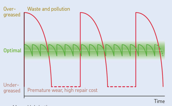
Getting spare parts inventory levels right usually delivers significant improvements in both cost and asset availability.  For the best companies, that is only the start, however. They monitor part consumption on an on-going basis to identify exceptions that may indicate an underlying issue with assets or operating practices. If a particular machine starts to experience an unexpectedly high number of early-life bearing failures, that might suggest an issue with improper assembly or lubrication. Spotting these trends in parts consumption allows the company to launch root-cause analysis efforts to understand and rectify the source of the problem.

A similar approach can be used to prioritise reliability improvement efforts. If a particular machine or category of parts is contributing disproportionately to consumable or operational part costs, the company may choose to launch a kaizen, or improvement, effort to tackle that machine’s performance and reliability. Alternatively it may consider the installation of condition monitoring technology to aid the early identification of problems, or could choose to invest in alternative technologies that offer greater reliability.

These efforts lead to a virtuous circle. As machine reliability improves and spares consumption falls, companies can alter their inventory parameters accordingly, freeing up further capital and reducing carrying costs.  And as overall usage patterns change, it becomes easier to spot the remaining outliers, helping to focus future improvement efforts.

Help from the experts
While the payback from better management of spare parts is usually large, the journey to world-class performance can be daunting. To help companies on their way, SKF has developed the Spares Inventory Management and Optimization (SIMO) service. Built on more than 100 years of deep experience in rotating equipment performance and asset management, bearing lifetime management   and supply chain management, SIMO provides a structured process designed to guide and support companies through every step of that journey.

SIMO is a four phase process, encompassing both the demand and supply aspects of spare parts management. It comprises spares identification and cataloguing, consumption forecasting, inventory rationalisation and on-going inventory optimisation.

As well as a rigorous, proven process, SKF brings important technical knowhow to the SIMO service. Clients can make use of standard spares templates for many common asset types, for example, aiding the development of a robust parts database. SKF has also built up a detailed benchmarking database of equipment performance across a range of industries, helping companies to pick the right forecasting models and to identify areas where their own equipment reliability or typical part service life falls outside of industry norms.

SIMO also integrates seamlessly with other SKF services designed to help companies minimize the total cost of ownership of their assets. Rather than buying individual bearings, for example, customers can use SKF’s “Bearings for Life” concept, in which they agree a price based on the total lifetime of an asset. SKF then supplies replacement components as required during that time, with SIMO calculations helping to determine appropriate on-site inventories. Likewise, SKF Logistics Services can use the same data to manage customer spares inventories on a consignment basis. And for every customer, SKF’s global distribution network ensures that huge number of spares are always available from stock or with short lead times, reducing the number of partsthey need to hold on site.

Every journey must start with the right first steps. To help companies to estimate the potential value of a shift to world-class practices, SKF has also developed CNA-SIMO (Customer Needs Analysis – SIMO), a simple but detailed needs analysis tool, allowing them to understand the current maturity of their spare parts management processes, and the principal opportunities for improvement.

Μοιραστείτε το άρθρο.....Share on twitter
Twitter
Share on facebook
Facebook
Share on google
Google
Share on linkedin
Linkedin
Share on email
Email

  • -

Why hygienic design of bearings is key to food safety

Category : News , Technical Articles

An emphasis on the hygiene element of the design of equipment can play an important role in controlling the safety of food products manufactured. However, applying this too broadly without focussing specifically on the hygienic design of the components part of the system, can potentially risk the spread of bacteria trapped within bearings, says Davide Zanghi, the person responsible for the Hygienic design office in SKF.

Hygienic design considers specifically how problems such as corrosion, lubricant leakage, cleaning and self-drying could adversely affect food safety – and applies design principles to solve the problem. In essence, it is a design philosophy applied through dedicated and specific rules. Just as ergonomic design pays close attention to the physical needs of product users, hygienic design has a laser focus on preventing issues of food contamination.

The European Hygienic Engineering and Design Group (EHEDG) aims to promote safe food by improving the standard of hygienic engineering and design, and includes equipment manufacturers, food companies and research institutes among its members. In November 2016, in Denmark, it ran its biennial World Congress. On this occasion, SKF – an EHEDG member since 2006 – highlighted its long record using these design principles.
Design principles – a dim view on bearing components

In general, EHEDG guidelines consider bearings an easy place to trap food particles and water and therefore these are seen as potential breeding grounds for harbouring bacteria. The advice is: keep bearings well away from food product contact areas.

This is very much the case with recent guidelines on hygienic design of belt conveyors for the food industry, where EHEDG addresses two of the major challenges in safe food production: how to avoid contamination of food through inadequately designed processing equipment and how to improve food safety without raising operating costs for cleaning and production hygiene. Even if lots of attention goes on systems design and major components such as belts; bearing and bearing units consistently have a low profile within the overall hygienic system design.

However, even if not in direct contact with the food zone, bearings are often in the proximity of food product and with high pressure water or dry cleaning regimes they pose the risk that bacteria – if present – can get airborne and potentially contaminate the food product.

In order to minimize the risk of contamination, designing bearings with hygienic design principles in mind is a key consideration. One of the most important principles underpinning hygienic design is the ability to clean effectively. This may be easy to understand, but it is often difficult to achieve in practice, for bearings and bearing units. For a start, the products should be made from non-corrosive and non-porous materials, such as stainless steel, or composites and with shapes that are cleanable, allowing self-draining. Bearing units should have filled bases, which removes cavities where germs may fester.

In general materials used such as elastomers and composite and grease should be compliant with food safety directives and regulations. In all instances, potential of grease leakage onto the food product during operation should be avoided.

Ideally, bearing units should have effective end covers – that prevent process contaminants and cleaning fluids from entering the bearing units cavity and, at the same time, allow a frequent visual inspection.

Other relevant areas are:

• avoid metal to metal contacts in between unit components and in between units and attaching surfaces
• avoid re-lubrication as much as possible
• achieve high service life despite of very demanding operating and cleaning regimes

Hygienic design applies to food production and packaging machinery in its entirety. But dealing specifically with one of the most problematic components – bearings – can only help to improve the overall risk strategy.

Μοιραστείτε το άρθρο.....Share on twitter
Twitter
Share on facebook
Facebook
Share on google
Google
Share on linkedin
Linkedin
Share on email
Email

  • -

Digitizing ship repairs: Why condition-based maintenance is gaining traction

Category : Technical Articles

The current situation in the maritime industry means ship owners are constantly looking for ways to reduce costs—while increasing safety and reliability. A condition-based maintenance strategy could help. But how does it work? And how can ship owners implement it successfully?

Choosing the right approach

CM solutions are vital to any CBM strategy. They work by using sensor devices to capture data on machinery and components: for example, accelerometers could measure the vibration of rotating components. Specialists then apply algorithms and their own knowledge to the data to analyze the equipment’s condition and identify any deterioration in performance.

There are two approaches to this: the data can either be collected periodically or continuously. The periodic approach relies on monthly or quarterly checks using portable devices. While this can be more cost-effective than continuous monitoring, there is the potential risk of issues going undetected in the time between checks. Therefore, continuous, real-time monitoring is typically applied to machines such as thrusters and alternators that are critical to operations or where repairs can be costly and time-consuming.

Continuous monitoring

  • Better suited to critical machinery
  • Real-time view of machinery conditions
  • More cost-effective in the long term
  • Conducted using online Systems

Periodic Monitoring

  • Typically used on non-critical systems
  • Provides advanced warning of failure
  • More cost-effective in the short term
  • Conducted using portable devices

The key to maximum reliability

Although they require more effort to implement on board, online systems for continuous monitoring have many benefits. When used in tandem with CM software, they provide integrated expert knowledge and automatic alerts based on detailed specifications. Specialists can quickly identify any faults and track their development to keep the machine operating in a safe and reliable manner. This not only helps ship operators to considerably reduce costs and minimize downtime, but also enables them to plan maintenance more efficiently and ensure the availability of replacement parts.

A CBM strategy can also extend inspection intervals. For example, a shipping company recently used the SKF thruster monitoring system on its thrusters to continuously monitor vibration and oil condition. By implementing a CM system, the company fulfilled the requirements of classification societies, extending the inspection interval from five years to seven and a half years. This saves an enormous amount of time and effort.

skf_zahl_kreis_element_3

Taking digitization on board

As maritime companies continue to adopt practices from other industries, CBM is now starting to gain traction in shipping. But digitization also contributes to its surge in popularity. Many ship operators are moving more and more data to the cloud to facilitate the sharing of information. This allows onshore experts to perform analyses and send their findings and recommendations to engineers onboard the vessel and onshore technical support teams.

Both trends look set to grow in the near future as shipping companies invest in ways to reduce total cost of ownership. By optimising ship safety, performance, and reliability, condition-based maintenance will certainly play a major role in the future of the sector.

Predictive, proactive, reliable

Cloud technology is revolutionising ship maintenance. Data can now be easily shared with more experts, both onshore and offshore, anywhere in the world. This helps them to make the right decisions at the right time and improve maintenance planning.

Μοιραστείτε το άρθρο.....Share on twitter
Twitter
Share on facebook
Facebook
Share on google
Google
Share on linkedin
Linkedin
Share on email
Email

  • -

Improved productivity and performance with automated lubrication

Category : Technical Articles

Proper lubrication is integral to ensuring the functionality of components and systems within heavy-duty machinery.

“If there’s a bushing, bearing or gear, something that is rotating or sliding in agricultural, construction and mining machines, it’s going to require lubrication,” says Peter Laucis, Director of Portfolio Management – ALS Products, SKF Lubrication Business Unit. “And the heavier the loads, the more aggressive and dirty the environment, the greater the need for lubrication.”

While manual lubrication is still the norm in many applications, use of automated lubrication systems (ALS) is becoming a more prevalent alternative to help minimise downtime, improve overall quality and safety through preventative maintenance.

With an ALS, lubricant can be applied exactly when and where it’s needed while the machine is running. Manual lubrication, on the other hand, requires the machine to be stopped before lubricant can be applied, and may require a person to climb onto the machine which can be a safety issue.

In addition to helping increase safety and productivity for equipment owners, Laucis says OEMs can also benefit from integrating an ALS into their equipment. “It can extend warranty and performance, and it can maintain the unit running at various conditions under the design the machine was geared to do.”

The systems and how they work

An ALS consists of a reservoir containing grease or other designated lubricant and an electric, pneumatic or hydraulic pump which activates the system to deliver lubricant from the reservoir to the desired location within the machine. Depending on the design of the machine, lubricant can be dispensed to as many as 100 or 200 different points. A series of metering valves are used to apply the lubricant in the desired location at the exact time lubrication is needed.

The system knows where and when to apply lubricant due to built-in controls. If the ALS is integrated into a machine at the factory, the system can be controlled by the OEM’s programmable logic controller (PLC). The appropriate lubrication intervals are programmed into the PLC, enabling it to turn on the ALS when necessary.

SKF also designs controllers which can be built into the system if it is added to a piece of equipment at the aftermarket level or another point along the OEM channel, such as by a dealer. Laucis says these controllers can provide simple on/off control or be more sophisticated through the inclusion of sensing devices to provide operators with information about when lubrication cycles are occurring, fault indicators and performance attributes.

Single line parallel and progressive are the two main types of lubrication systems used within heavy-duty mobile applications. A single line parallel system consists of a reservoir and a pump connected to a bank of injectors by a single hose line. The injectors are lined up in parallel with one another, like fingers on comb, and each of the injectors function independently of one another. By doing so, each injector meters the exact amount of lubricant required and can also be adjusted independently if necessary.

The independent functionality is beneficial because if one bearing fails or gets blocked in some manner, it will not adversely affect lubrication of other bearings in the machine. “People like the single line parallel because they can lubricate the entire machine of, let’s say 120 points, and when a couple of those points fail, they’re still getting lubrication in the other systems,” says Laucis.

He notes these systems are often used in heavy mining equipment due to the need to minimize downtime as much as possible. It can also be used in construction equipment to avoid poor operator maintenance and in agricultural equipment for safety and bearing protection.

Progressive systems are similar, except the single line goes to a series of valve blocks instead of a parallel line of injectors. Each valve block meters lubricant to various points within a machine; one block may have up to 12 points to which it provides lubricant, and the next block or zone will lubricate another 12 points, and so on. “The main difference is if you have one bearing that blocks, it literally stops the entire system because the grease is progressing through the system in a series,” Laucis says. “If you block one bearing it will actually have a hydraulic lock on every piston in that block in the system, then the whole system shuts down.”

He says this type of system is typical for medium-size machines such as those used for highway construction because customers like that a fault indicator will come on when a blockage occurs, letting them know to check the machine at the end of the work day. While downtime is a concern, it is not as important as in mining operations where even the smallest amount of downtime can adversely affect productivity and thus profit for the customer.

Multiline systems can also be used in off-highway machinery. This system consists of a round housing with several points—up to 20—coming out of it, each of which goes to an individual bearing or other component to lubricate. The system is designed to simultaneously feed several points within a short distance. Laucis says this system is typically used in smaller, less heavy-duty applications due to the fact that it’s not necessarily the most cost-effective option. Since the system is limited on how many on points it can feed, a larger machine would require several systems to be installed, whereas the single line systems are more modular and better able to feed a larger number of points from a single source.

Moving toward more automation

Use of an ALS is becoming more prevalent within the heavy equipment industry, however, Laucis says it can be difficult in some applications to compete with an individual who manually lubricates a machine. In large, heavy-duty machines—such as mining equipment—he says there is a high rate of adoption because much of the equipment is automated to maintain performance levels and eliminate or minimize downtime, which can be aided by an ALS.

He says safety is also a factor for increased use of these systems in heavy machinery. “People are becoming really safety conscious. They are preventing or minimizing the environments where there’s danger, and lubricating points on a machine is a safety issue.” Eliminating the need to manually lubricate parts of the machine ensures a person will not have to climb all over the machine—which may be covered in dirt and grease—and risk possible injury. “You also have mechanical shut off devices, automatic sensing for high/low level grease levels,” says Laucis. “All these accessories are now becoming more prevalent and required on automatic lube systems because they will promote safe environments, continuous uptime performance and be able to provide a nice clean machine.

“In the medium machinery market, where cost per point is becoming more critical, I would say the market is stabilizing and increasing based on the value of performance,” he continues. This is due in part to the ability to add telematics to the lubrication system, enabling customers to receive feedback on performance and servicing like they do with other systems in their machine. Increasing safety has also caused the rising use of automated lubrication systems in these machines.

On smaller sized machines, Laucis says manual lubrication is still the norm as end users typically have regularly scheduled maintenance they perform, making it easy to have lubrication be a part of that maintenance regimen. However, he does see the rate of adoption for ALS increasing in this segment, as well.

Whether the system is installed at the OEM or aftermarket level is also dependent on the type of machinery in which it will be used. On larger machines, the OEM tends to install the ALS at the factory. As machine size starts to decrease, the use of auto lube become options depending on the customer preferences and use of the machines in their environment. OEMs look to a strong aftermarket “pull” by their customers to standardize their ALS factory fit systems.

On the aftermarket side, he says it’s important to look at what value there is for the customer to add the system, such as safety and performance benefits. For a rental fleet, the case could be made for using the systems to help maintain inventory. If a rented machine comes back and is not performing as it should, the ALS’s data logger can verify whether or not the machine was properly lubricated to help narrow down what may be causing the issue. Laucis says having strong aftermarket support and proof of ROI on the end user side can lead to an OEM seeing value in integrating the system at the factory.

Since SKF also designs and manufactures bearings, the company is able to use its knowledge of how they work, and what causes them to fail, in order to explain the benefits of moving to an ALS. One of the most common performance issues with bearings is the lack of lubrication and they are dirty. “The best way to prolong the life of a bearing is to have a continuous, thin film of lubricant at all times,” says Laucis. “We have studies and other information to say if you continually lubricate with small intervals, you will have the longest performance of a bearing.”

An automated system is able to provide that continuous lubrication, whereas manual lubrication would require a person to stand by the machine while it’s running and move a grease gun to every point requiring lubrication, and apply grease every minute says Laucis. Often times manual lubrication is completed at the end of the work day or week, and the lubrication point is flooded with grease or the worker only applies a few pumps of grease and then goes about his or her business. This causes long intervals between lubricant applications, which he says is not the best way to prolong the life of a bearing.

“And that’s the philosophy of automated lubrication versus other methods that has to be sold and promoted to maintain machines on a longer level,” says Laucis. Through the use of an ALS, both OEMs and end users can benefit from the system applying only the amount of grease a bearing requires and at the exact time it’s needed, ensuring the bearing will perform as designed and machine downtime will be minimized.

The original article written by Sara Jensen/OEM Off-Highway can be found here: http://www.oemoffhighway.com/article/12250664/automatic-lubrication-systems-increase-machine-performance-and-reduce-downtime.

Μοιραστείτε το άρθρο.....Share on twitter
Twitter
Share on facebook
Facebook
Share on google
Google
Share on linkedin
Linkedin
Share on email
Email

  • -

The progression of surface rolling contact fatigue damage of rolling bearings

Category : Technical Articles

The mechanism of surface rolling contact fatigue in rolling bearings is investigated by means of dedicated experiments and numerical simulations of the damage progression.

Rolling contact fatigue (RCF) is a typical failure mode in rolling bearings and similar types of machine components. The fundamental work in RCF is due to Lundberg and Palmgren [1], [2]. The Lundberg-Palmgren theory was mainly focused on subsurface rolling contact fatigue, and it relies entirely on ideally smooth Hertzian stress calculations. Surface rolling contact fatigue (SRCF) instead involves the area close to the surface of the contact (a few microns deep) that is strongly affected by local surface traction and stresses originated from geometrical features of the surface such as roughness, profile deviations, indentations, etc. The interaction between the elasto-hydrodynamic lubricating (EHL) film and the actual features determining stress risers at the surface is very important in the understanding of surface fatigue phenomena of rolling bearings (Morales-Espejel and Gabelli [3]). In this article, the progression of SRCF is investigated by modelling the contact and the interaction with deviations of the surface micro-geometry that generate stress concentrations. Comparison of the numerical simulations with a set of experimental results indicates good correlation, allowing the formulation of a hypothesis about the underlying mechanisms of SRCF, as well as its inception and growth in rolling bearings. This new knowledge fits very well with the basic idea behind the SKF Generalized Bearing Life Model (GBLM) that separates surface from subsurface fatigue damage [4][5].

Theoretical investigations in damage progression
Often, rolling contact fatigue damage originated around surface microgeometry features develops into a spall. Spall propagation, in its advanced form, is strongly influenced by macrogeometry aspects – for example, the evolution of the raceway contact geometry and resulting overall stress field in a rolling bearing. Several researchers have studied spall propagation in rolling bearings in the attempt to associate the mechanical aspects driving the damage progression.

A recent investigation carried out by the present authors [6] has studied SRCF propagation of predented rolling bearings, both with a model and experiments, concluding that the mechanisms involved in ball bearings require the consideration of lubrication conditions and the interaction of stresses between the surface and subsurface to understand the development of the typical V-shaped cracks along the raceway, differently from the initial transverse damage growth observed in roller bearings that can be explained sufficiently with only dry contact assumptions.

Experimental observations in damage progression
Snare [7], in his statistical analysis of bearing reliability, monitored the propagation of a spall in a cylindrical roller bearing, showing the clear progression of the damage across the raceway before the spall starts to propagate along the raceway. Fig. 1 shows the experimental tests of Snare.

Current understanding
From the theoretical and experimental investigations found in the literature, at least two distinctive spall propagation phases from surface defects are clearly recognized. The first one is when the spall grows across the raceway at a more or less slow rate, and the second is when it grows along the rolling path in a more accelerated fashion. The reason for the across-raceway propagation of the spall, in its initial phase, is understood as a consequence of the higher stresses present at the diametral edges of the spall – that is, along the direction orthogonal to rolling, compared to the stresses at the spall leading and trailing edges.

The behaviour of the spall inception and propagation on ball bearings (fig. 2) and roller bearings (fig. 3) is strikingly distinct. Surface-initiated spalls in ball bearings initially develop with a characteristic V shape at the trailing edge of the indentation, rapidly growing in the rolling direction with the detachment of raceway material from the V-shaped area. The growth of the spall is observed in the rolling direction, which is the direction opposite to the direction of friction and slip present at that location (fig. 2). Surface-initiated spalls in roller bearings initially propagate at the two sides of the original initiation spot, growing across the raceway before expanding along the raceway (fig. 3).

The objective of this article is to shed further light on the progression of surface-initiated fatigue damage of roller bearings. This is to understand via modelling the driving mechanisms behind the damage propagation as observed in the experiments, as a continuation of the work reported by the authors [3], on the initial damage phase, but now focused of the propagation of this damage.

Experimental work
Experiments were conducted on standard tapered roller bearings; see table 1.

Tapered roller bearings were artificially indented using an indentation load of 1,250 N and a 1 mm diameter tungsten carbide ball indenter. This load provided dents with a diameter of 400 µm, 30 µm dent depth, and a raised edge height of about 2 µm. The experiment consisted of eight equally spaced indentations around the circumference on the inner ring of the tapered roller bearings. The dents were also spaced at 0.5 mm steps across the raceway, starting from the raceway edge. However, in this article, only the progression of damage of the dents located at the centre of the raceway will be discussed in detail. Under the operating conditions given intable 1, the axial load provided a Hertzian width in the rolling direction of about 142 µm, which is substantially narrower compared to the dent diameter. The experiments were run at different numbers of revolutions to observe the progression of the fatigue damage, resulting from the stress concentration and lubrication conditions of the dents.

Fig. 4 shows some experimental results about the progression of the dent spalling in the tapered roller bearing for an increasing number of revolutions. The spall initiated at one side of the dent and then progressed towards the two sides of the dent across the raceway – that is, along the direction orthogonal to rolling. In fig. 4(b) an approximated contact ellipse was drawn for comparison with the final spall. Several inner rings were monitored by periodic microscopic inspection performed on each bearing, at about 5 million revolutions apart, to detect the initiation and propagation phase of the spall. Each dent was microscopically inspected and photographed as a function of the number of revolutions performed in the test. The initial development and further progression of the spalled area around the dent were measured by digital image processing of the collected microphotographs from several individual dents. The results of this detailed investigation provided very precise information about the initial and progressive growth of the spalling damage area against number of revolutions.

All the data collected from the six individual dents that developed spalling damage are shown infig. 5.

A more detailed inspection of the average test data indicates that the progression of the spalled area follows a three-stage process:

1. The incubation time of 50 to 60 million revolutions in which no apparent visible damage can be detected in the bearing raceway; this is about the fatigue rating life of the bearing.
2. The initial damage progression phase, which extends for 30 to 40 million revolutions, as expected, displays an exponential growth of the damaged area.
3. The accelerated growth. This extends for 20 to 25 million revolutions, during which the growth rate substantially increases (more than twice compared to the previous period).

Damage propagation model
Calculation of the damage in the rolling contact is carried out by modelling in the first instance the initial indentation of the raceway. This is done using a parametric analytical function that closely reproduces the shape of the actual dent.

The dent geometry is then included in an overrolling contact model to reproduce the Hertzian cycling stress of the actual test bearing. The damage progression calculation is performed using the basic surface fatigue and detachment model developed previously by Morales-Espejel and Brizmer [8] and fully described there. However, some modifications and adaptations were also introduced. For instance, the routine for wear calculation, as described in [8], was switched off to accelerate the speed of the numer-ical simulations. The fast lubrication model is switched off, and only the dry contact model is used for situations where the initial indentation is wider than the Hertzian contact in the rolling direction, which is the case for the simulated tapered roller bearing of fig. 4(a). The model is then used in the calculation of the overall pressures and stresses. This approximation is valid because in this case the lubricant is likely to escape from the dent and contact. No generation of hydrodynamic pressure is to be expected at the dent edge region whose pressures can therefore be modelled using the dry contact hypothesis (for ball bearings with wider Hertz contact area, the lubrication model cannot be ignored).

Once the contact pressures are calculated, the stress history is obtained for a series of time steps designed to simulate the passage of the indentation through the rolling contact (see [5]). From this multistep simulation process the fatigue stress history can be computed for further processing by the fatigue criterion in order to estimate the fatigue damage accumulated from the start to the current load cycle. This scheme follows exactly the same data processing introduced by Morales-Espejel and Brizmer [8]. The total damage accumulated up to the current load cycle is calculated following the Palmgren-Miner rule.

When fatigue reaches a critical damage value, the possibility of an onset of material fracturing emerges. The current scheme does not have a detailed crack propagation model; the damage propagation is simulated by simply removing fatigued material. For this purpose, a simple material detachment model [8] was implemented that performs the task of removing the material with accumulated critical damage and material above it. This model contains also a threshold depth (h) from the surface below which material with critical damage is not allowed to detach. This threshold depth can be set up from h = 0 to h = ∞.  Setting h ≥ 0 will allow material below the surface to detach. The current model cannot give a precise indication of the damage growth if the parameter h is not known in advance or if some experimental results are not available, but it can very well describe damage growth ranges as will be shown below. The calculation process is repeated for a given number of load cycles (up to a maximum, typically > 109 overrolling cycles), after which the damage progression history is reported.

Model results
Test data are given in table 1. In this case the dents are wider (i.e., diameter 400 μm) than the Hertzian contact in the rolling direction (i.e., 142 μm); therefore, it will be impossible during overrolling to develop the required EHL pressure over the dent. This will induce a collapse of the oil film at the edge of the dented area. Under these conditions, the effect of the lubricant film can be excluded from the analysis, and the progression of damage can be simulated simply using the dry-contact approximation.

Fig. 6 shows the spall evolution from the initial indentation for an increasing number of revolutions; they also show the progressive changes of the Hertzian pressure and related subsurface stresses. The results of the numerical simulations clearly show the preferential direction of the progression of the spalled area. The damage starts from the dent lateral edges and progresses in the axial direction across the raceway in a similar manner to the one observed in the experiments (see fig. 4). By computing the area covered by the damage and its evolution with the number of bearing revolutions, it is possible to obtain the curve of the progression of the damage area versus number of revolutions of the bearings. This was computed for two threshold depth levels, h, a minimum and a maximum to characterize the scope of the model simulations (hmin just touching the area of maximum orthogonal shear stress around the dent and hmax well beyond that). The resulting damage progression curves are shown with dashed lines in fig. 5. A thin dashed line is the result of the most conservative setting for the estimation of surface-initiated microspalling – that is, minimum value of the threshold depth. Therefore, the simulated results represent a safe bound of the damage, defining the conditions for the maximum expected damage area from any surface-initiated spall.

With the implementation of a maximum threshold depth value, h, the evolution of the damage shown in fig. 5 with a thick dashed line shows a more realistic match with the experimental results. Noticeable is the initial trend of the computed damage area, which shows a stepwise progression clearly matching some of the experimental measurements. This trend achieves a stable growth rate of between 90 and 120 million revolutions; this interval can be compared to the measured initial progression phase of the damage growth of the dent as discussed in the section “Experimental work”.

Fig. 7 shows the damage growth rate of the experiments compared to the one obtained from the numerical simulations, which is 11.5 million revolutions (134 million cycles). This good correlation between the average of the experimental results and the numerical simulations shows the ability of the computation to capture some principal effects of the surface fatigue mechanisms and of the initial spalling progression. In addition, the experimental results indicate an accelerated growth after 100 million revolutions that seems absent from the results of the numerical simulations. A possible explanation of this behaviour is that the generation of a spalled area also results in additional loads due to the dynamic response of the bearing to the spalling damage. At the moment, these additional loads are not included in the model; thus, only the initial spalling damage can be reasonably compared with the numerical
simulations.

In the simulated results the mechanism of the damage progression is also interesting. Because the indentation is a bit larger than the Hertzian width in the rolling direction, the most loaded zone in the raceway is the lateral area of the indentation, where the damage indeed will initiate and progress. This propagation mechanism can also be found in the numerical simulation showing the lateral edge of the spall affected by the largest surface pressures and subsurface stress concentrations (fig. 6). This type of spall propagation seems to be typical of roller bearings.

Discussion and conclusions
Experiments have been carried out on tapered rolling bearings. The raceways of the bearings were indented with predefined hardness imprints. This created a series of surface stress risers from which surface spalls were originated, allowing the detailed study of their inception and progression. An existing model for surface microgeometry fatigue (Morales-Espejel and Brizmer [8]; i.e., surface distress) was adapted to study the surface-initiated macro-spalling process.

The model was applied to gain better insight into the initiation and early propagation phase of the spall. From the computational results it is found that indeed the numerical model can simulate and explain well many of the experimental observations; in particular the experimental results have indicated that in case of the tapered roller bearing, the spall propagates initially across the raceway – that is, along the direction orthogonal to rolling. In general in line-contact bearings, the stresses are higher at the lateral edges of the indentation. These higher stresses drive the growth of the spall across the raceway during the initial expansion of the spall.

From the results of the current work, the following conclusions can be drawn:

1. Pre-indented roller bearings propagate spalls initially across the raceway, driven by the higher stresses found at the edges of the spall along the direction orthogonal to rolling, as previously described in the literature.

2. The presented model describes well the two spall propagation mechanisms. For roller bearing spalls in particular, a good correlation between the model prediction and the experimental measurements is found in the initial spall growth rate.

Acknowledgment
The project was partially financed by the European Commission Marie Curie Industry-Academia Partnerships and Pathways (IAPP) – iBETTER Project.

Μοιραστείτε το άρθρο.....Share on twitter
Twitter
Share on facebook
Facebook
Share on google
Google
Share on linkedin
Linkedin
Share on email
Email

  • -

High performance polyurethane seals for wind turbines

Category : News , Technical Articles

Wind power has entered the mainstream. By the end of 2014 global wind generation capacity had reached 369.6 GW according to Global Wind Energy Council.

The share of wind energy in electricity production is expected to increase the coming years as wind has become increasingly competitive. Demand for wind will also shift to developing countries where there is an increasing demand in electricity.

To keep delivering on its potential, however, the global wind energy industry must maintain high levels of reliability and availability. As the number of turbines in use worldwide increases, operation and maintenance is becoming an ever more significant business. It is a challenge that is compounded by the fact that turbines are often installed in remote places, from mountaintops to offshore locations.

In modern wind turbines, the main shaft seals provide the first line of defence between the external environment and the critical main bearings and gearbox components. These seals play a dual role: protecting turbine components from contamination and stopping lubricants escaping into the environment. Now engineers at SKF have developed a new generation of seals – the HRS range – specifically to meet the challenges of the wind energy industry.

Light, compact and versatile

The machined polyurethane HRS seals weigh less and take up less space than labyrinth seal designs – a characteristic appreciated by equipment manufacturers looking to maximise space utilization and minimize the weight of turbine nacelles. They are available in three different designs to suit different applications. The HRS1 seal is designed to keep lubricant inside the turbine’s bearing and gearbox, while coping with the large misalignments experienced in this kind of equipment. Depending on the size of the shaft, HRS seals can accommodate coaxial misalignment of up to 3mm. For applications where protection from external contamination by dust or moisture is also a priority, customers can add the HRE excluder seal to the HRS1, providing an additional external lip. Alternatively, they can use the HRSA version of the seal, which incorporates an auxiliary lip into its design.

The HRS seals are manufactured from G-ECOPUR polyurethane, which is an ozone, UV and water-resistant material that offers excellent wear resistance compared with the rubber materials commonly used elsewhere. In tests, the G-ECOPUR has proved to be five times more abrasion resistant than the next best performing elastomer material, a characteristic that translates into longer service life and less chance of premature failure. G-ECOPUR also allows the HRS seals to be machined with an exceptionally smooth surface. This means that the seals have less of a tendency to make grooves in the surface of the shaft, helping to maintain system performance over the life of the turbine. The seals’ smooth outer surface, meanwhile, also prevents the leakage of lubricant between the seal and housing, a condition that commonly affects rougher phenol-impregnated fabric seals.

“In wind turbine design, seals haven’t the highest priority,” says María Concepción Martín Product Manager, Wind Energy at SKF. “But they have a high impact on system performance, which is why they have been an important area of focus for SKF. The new HRS machined polyurethane seals have been developed to deliver exactly what the wind energy industry needs: greater turbine reliability with reduced maintenance requirements in a cost effective package. And when seal replacement is eventually needed, these seals offer a quick, easy and safe solution.”

A breeze to fit

The whole HRS range is available in solid or split designs. Solid seals are designed for installation during manufacture where operators can access the end of the shaft. Split seals are ideal for in-service replacement, or manufacturing applications where there is no access to the end of the shaft. The smooth outer diameter of the HRS seals also makes them easier to install than fabric reinforced seals, saving time and cost in manufacture or replacement.

Carefully optimized seal geometry means the sealing lip cannot contact the seal carrier, so minimizing the risk of inverting the seal or losing the stainless steel garter spring during assembly. Meanwhile, the design of the seals themselves, with stiffer materials further simplifies installation, saving up to four working hours per seal compared to alternative fabric designs.

For maintenance and repair applications, the split HRS seals are provided in special transport packaging that contains all the materials necessary to complete the job, a boon for service teams working in cramped and remote conditions.

Wide availability

HRS seals are manufactured in a full range of standard sizes to suit modern wind turbine applications and can also be made to meet specific customer requirements. The seals are already available through SKF’s worldwide distribution network, helping to support manufacturers and operators that are working on an increasingly global basis. They can also be supplied as part of an integrated SKF solution that includes bearings, seals and lubrication.

Μοιραστείτε το άρθρο.....Share on twitter
Twitter
Share on facebook
Facebook
Share on google
Google
Share on linkedin
Linkedin
Share on email
Email